Honors Advanced Topics in Engineering Daily Log
Welcome to my daily log for Senior Engineering! Here, I will outline what I do every day in class.
Navigation
| September | October | November | December | January |
|---|---|---|---|---|
| February | March | April | May | June |
September
09.03.2025
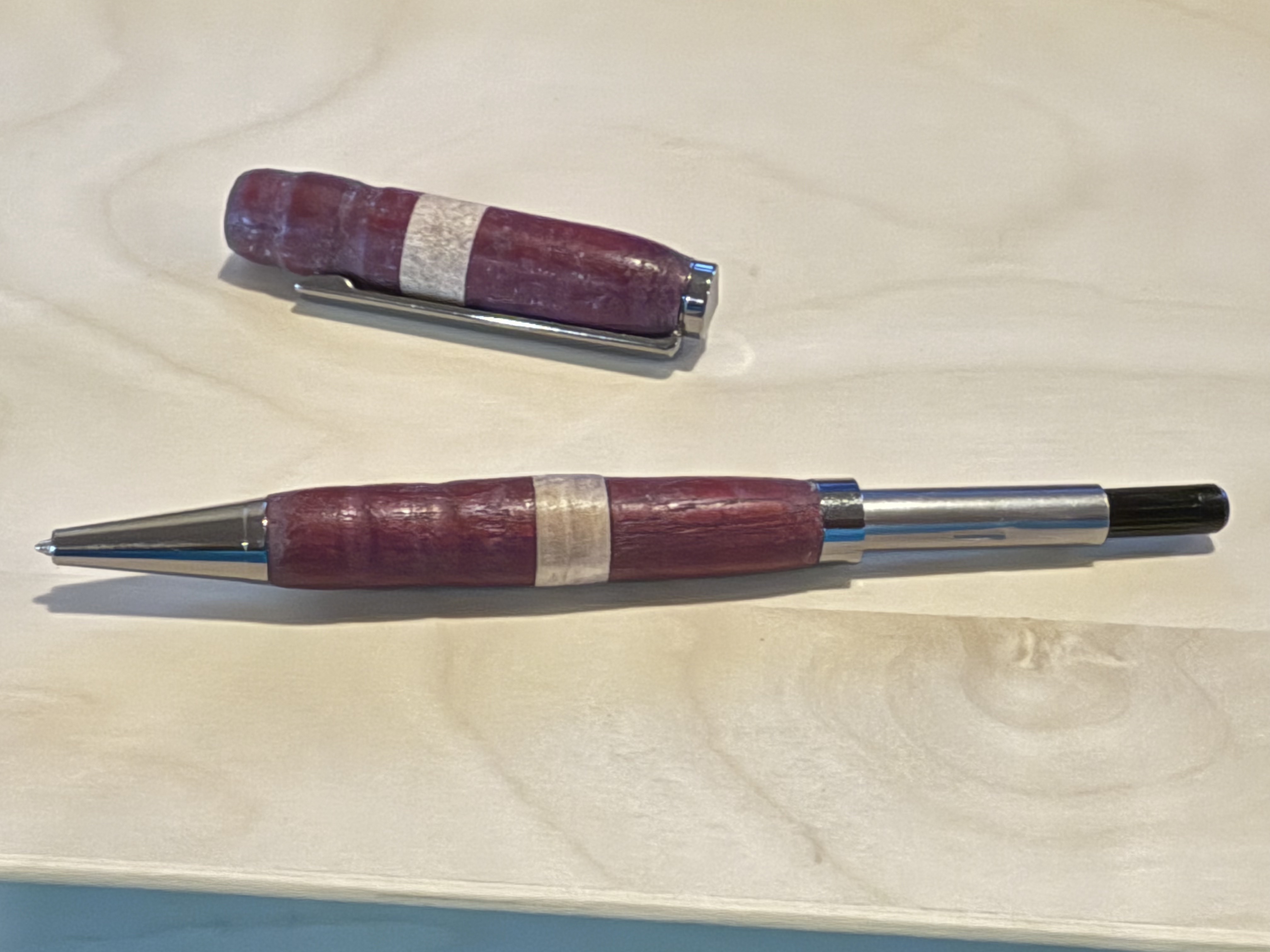
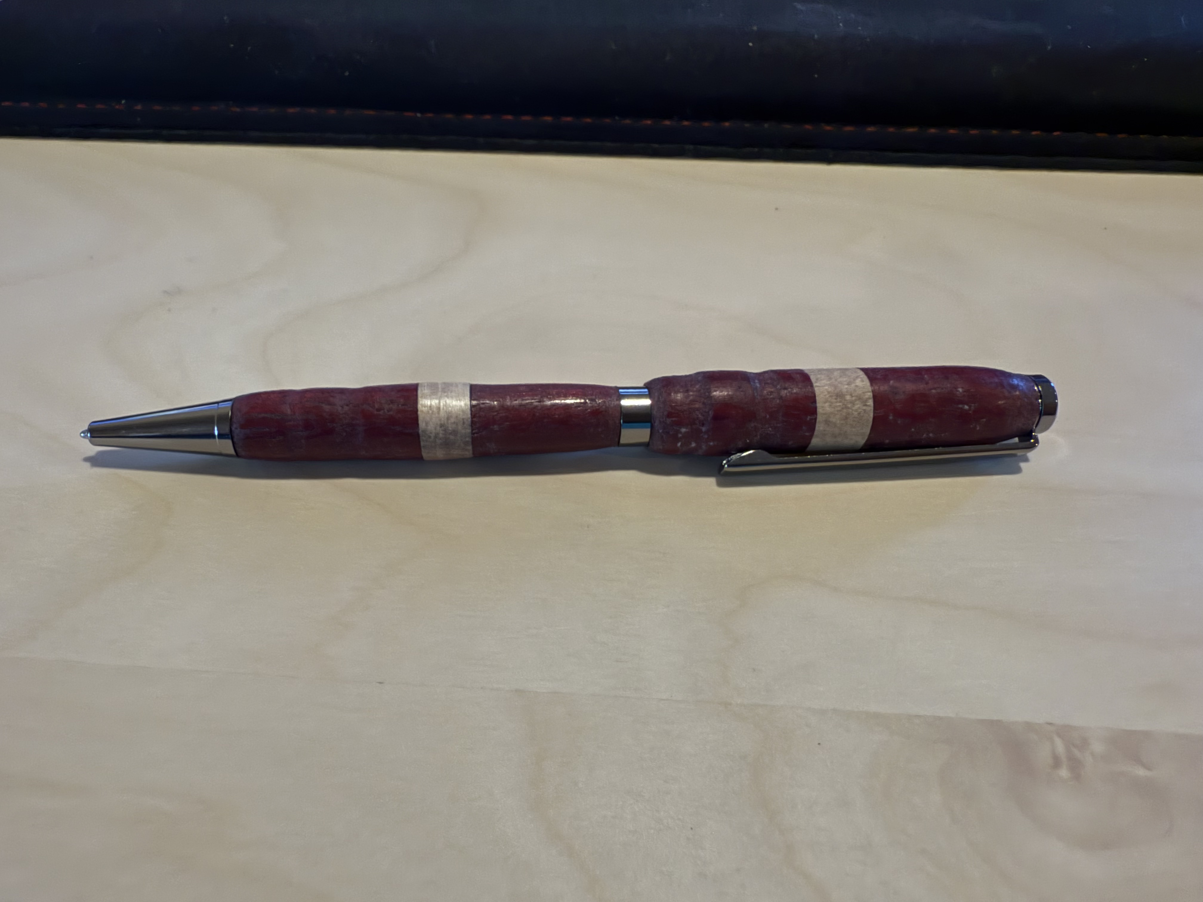
Today, I continued work on my wooden pen. I took my two blocks of wood and turned them on a lathe. I took a chisel and removed material until the blocks were cylindrical, and when they got to the desired thickness, I used fine grit sandpaper to smooth the two blocks. Now, I have the two wooden components for my pen ready, and now, I can assemble the pen and do all of the finishing touches next class.
09.04.2025
Today, I finished my pen. I started off by using the pen press to:
- Press the pen tip into the bottom end of the lower barrel
- Press the ink chamber into the top end of the lower barrel
- Press the clip assembly into the top end of the upper barrel
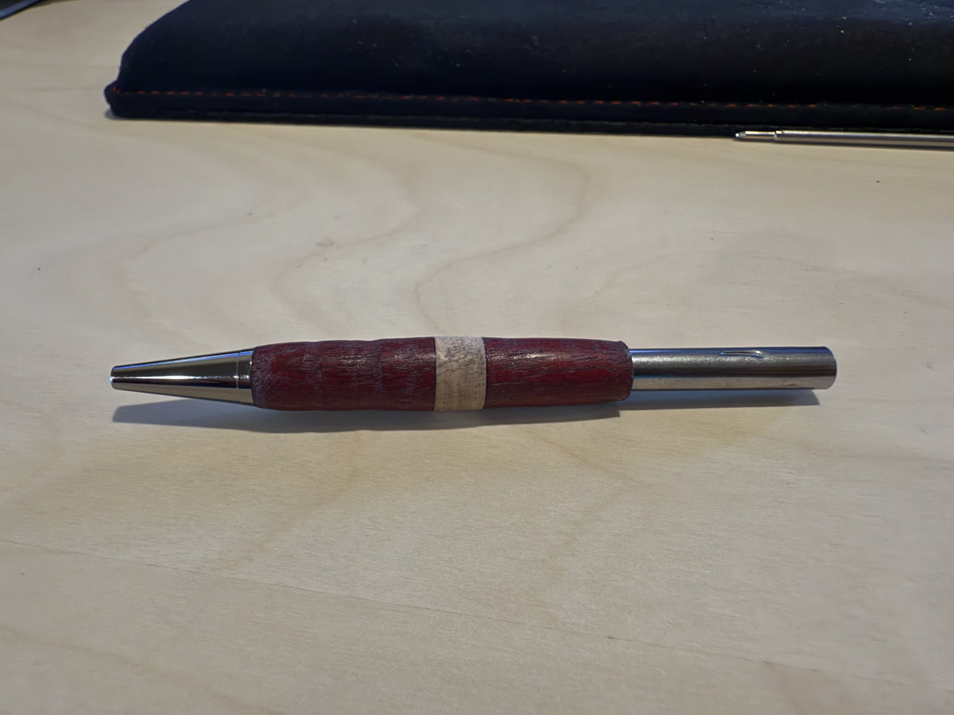
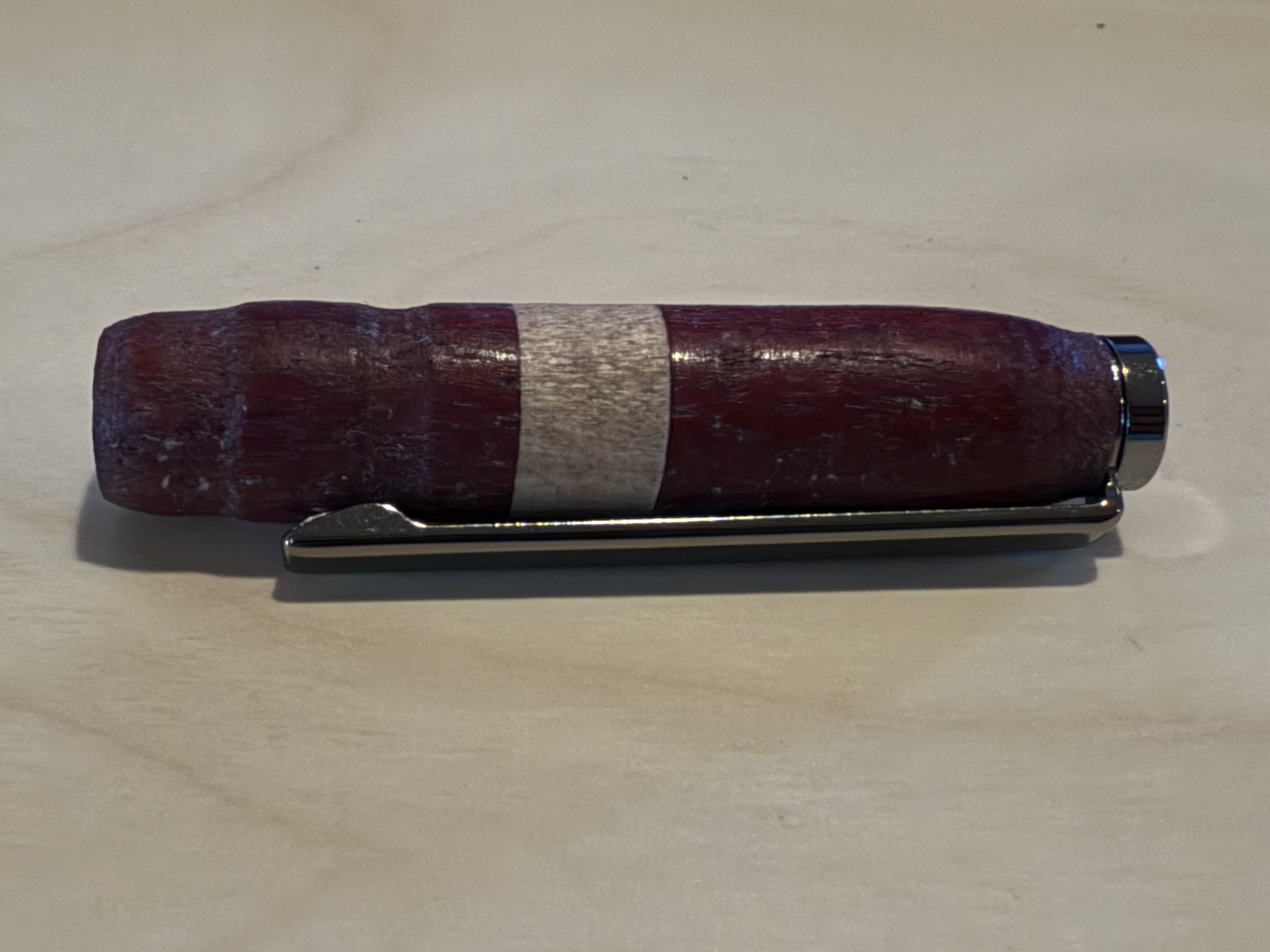
Once I pressed these components, I could assemble the main sections together. I screwed the ink refill into the ink chamber, slid the ring onto the chamber above the lower barrel, and slid the upper barrel above the ring. Once I did that, my pen was done, and it wrote super well, along with looking very cool.
09.05.2025
Today, I did some research and work on my capstone project. My goal is to assemble the board as soon as possible, so today, I practiced soldering random components to practice boards to prepare for soldering intricate components on the board.
09.08.2025
Today, I researched more about how to configure ArduPilot for a custom board. I decided that I would have to compile ArduPilot from the source code with a custom hwdef.dat file for my specific hardware configuration. From the start, I knew that I wanted to do as much as possible in VSCode, as I am very familiar with it. After doing some researching, I discovered that ArduPilot provides a VSCode integration which allows you to configure and flash ArduPilot directly from VSCode. All I have to do is make a custom board definition (hwdef.dat) for my specific hardware detailing what components I have and how they are connected, then I can use that board definition in the ArduPilot configurator to flash it.
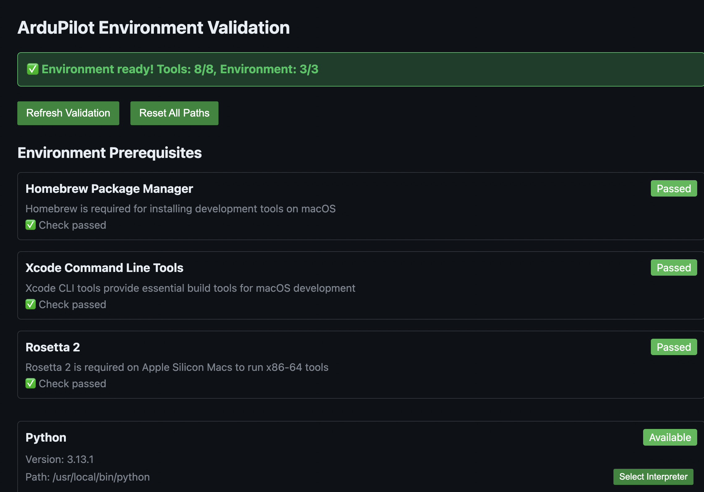
Conveniently, the extension has a built-in tool to make sure that your machine's ArduPilot environment has all of the necessary tools to build and flash the software. I had to install a lot of stuff, such as:
- Python MAVLink (
pip install pymavlink) - MAV Proxy (
pip install mavproxy) - J-Link (through SEGGER application)
In addition, I had to create symlinks between ccache and g++, gcc, arm-none-eabi-gcc, and arm-none-eabi-g++. I did so by adding this line to my ZSH profile (~/.zshrc: export PATH="/opt/homebrew/opt/ccache/libexec:$PATH", then verifying that the installations of ccache, gcc, g++, arm-none-eabi-gcc, and arm-none-eabi-g++ were correct by typing which + the name of the toolchain.
I made sure that they were all installed, but I was unclear as to what exactly their purpose was. I did some digging and these were the results I found:
- GCC: GNU Compiler Collection's C compiler
- G++: GNU Compiler Collection's C++ compiler
- arm-none-eabi-gcc: Compiles .c code into machine code for the ARM Cortex-M family of CPUs
- arm-none-eabi-gcc: Compiles .cpp code into machine code for the ARM Cortex-M family of CPUs
Together, these toolchains work together to compile the .c and .cpp files that make up the ArduPilot source code in order to create machine code for the ARM Cortex-M CPU that powers my flight controller (STM32F767ZIT6).
 { width=400 }
09.09.2025
Today, I did some more research on how to set up the software. I read the ArduPilot documentation, STMicroelectronics documentation on their various apps such as STM32CubeMX, STM32CubeIDE, etc. They have many apps, so it was confusing trying to figure out exactly what purpose each app had and whether or not I needed them. The only STMicroelectronics app that I will need is the STM32CubeProgrammer which will allow me to flash the ArduPilot software to the STM32 with an ST-Link via Serial Wire Debug.
09.15.2025
I dedicated today to working on my GitHub documentation. Mr. Dubick taught the class on how to use GitHub, and I worked on refining format and writing out some pages on Github.
09.16.2025
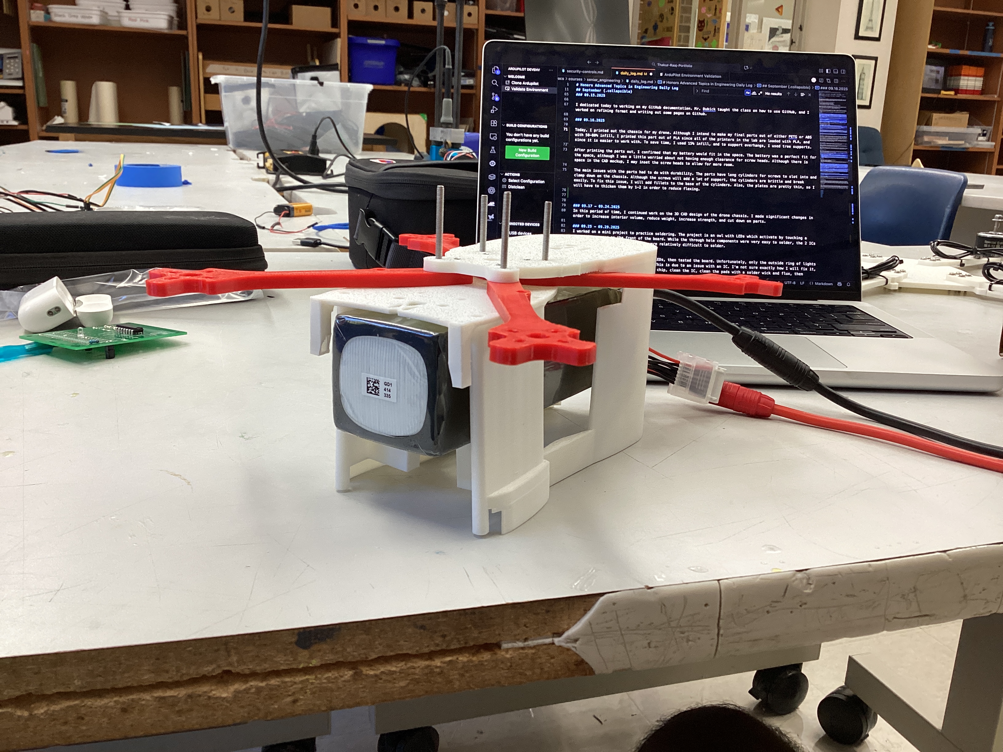
Today, I printed out the chassis for my drone. Although I intend to make my final parts out of either PETG or ABS with 50-80% infill, I printed this part out of PLA since all of the printers in the lab are loaded with PLA, and since it is easier to work with. To save time, I used 15% infill, and to support overhangs, I used tree supports.
After printing the parts out, I confirmed that my battery would fit in the space. The battery was a perfect fit for the space, although I was a little worried about not having enough clearance for screw heads. Although there is space in the CAD mockup, I may inset the screw heads to allow for more room.
The main issues with the parts had to do with durability. The parts have long cylinders for screws to slot into and clamp down on the chassis. Although the screws will add a lot of support, the cylinders are brittle and break easily. To fix this issue, I will add fillets to the base of the cylinders. Also, the plates are pretty thin, so I will have to thicken them by 1-2 in order to reduce flexing.
09.17 - 09.24.2025
In this period of time, I continued work on the 3D CAD design of the drone chassis. I made many small changes in order to increase interior volume, reduce weight, increase strength, and cut down on parts. However, I never printed it out since I was not happy with the final result (and eventually I made a new design from the ground up, more on this later).
09.25 - 09.29.2025
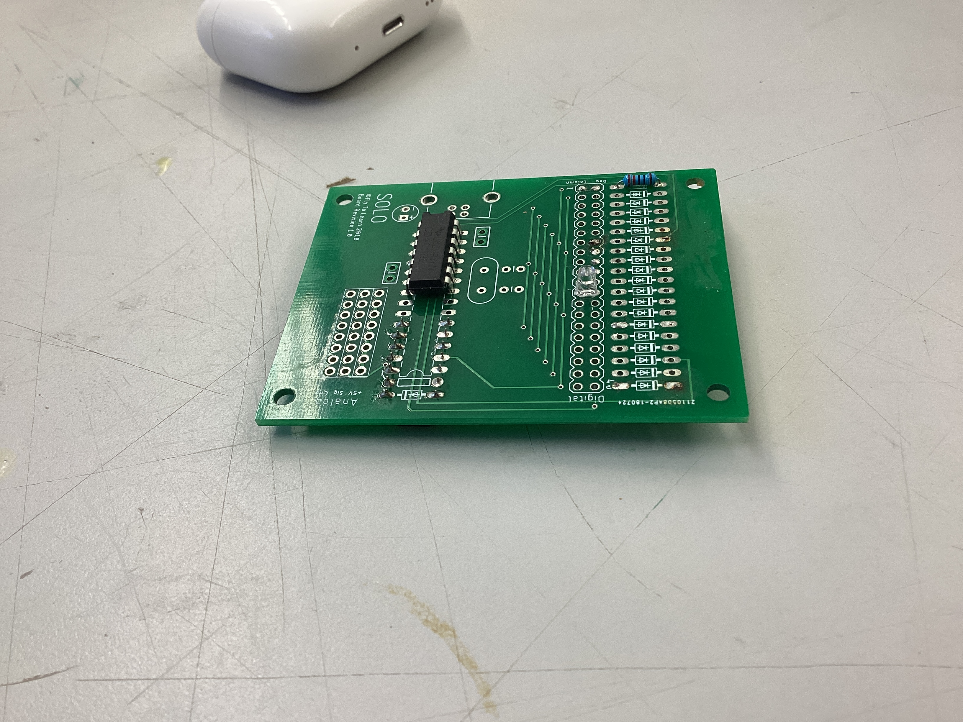
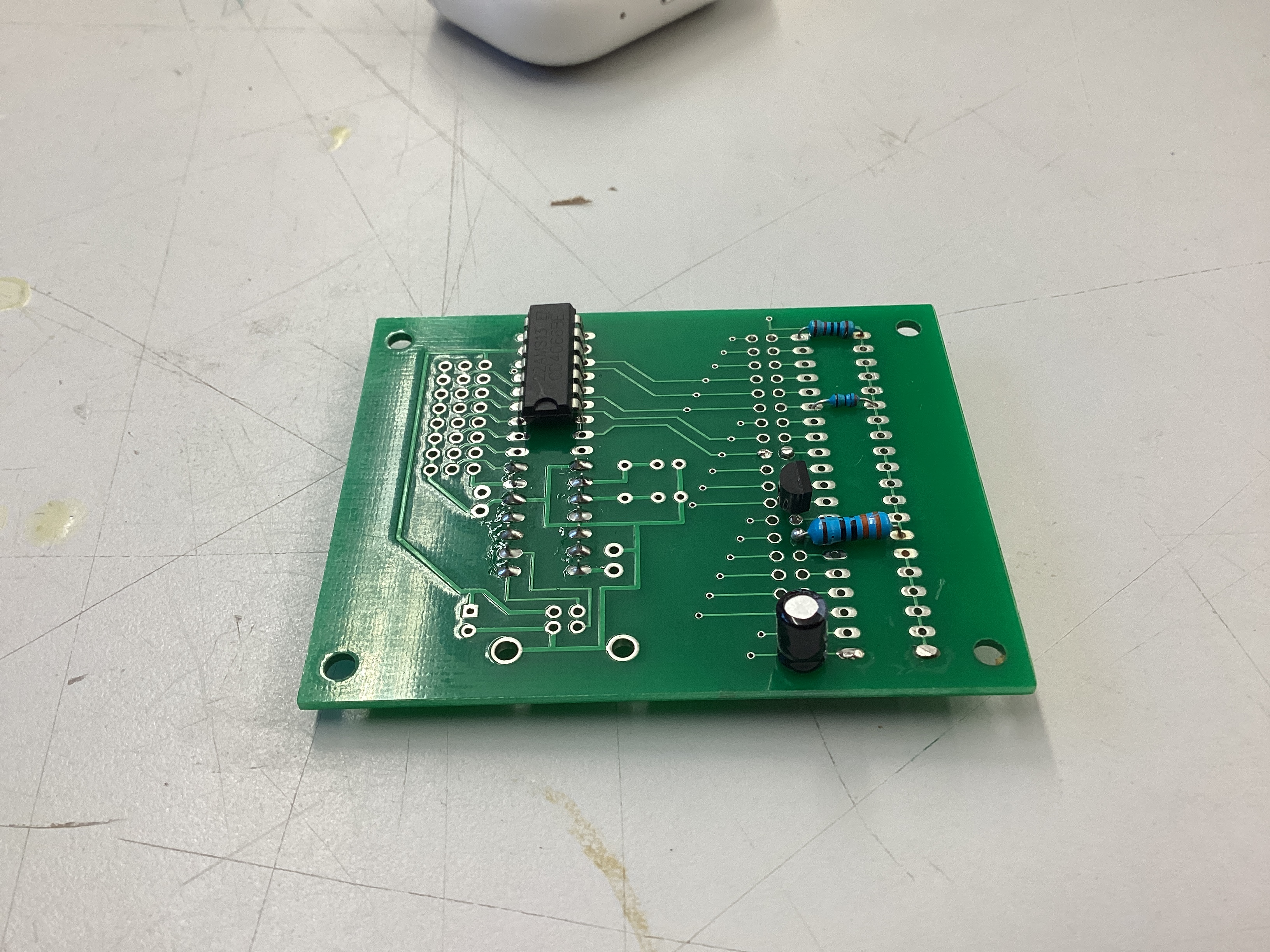
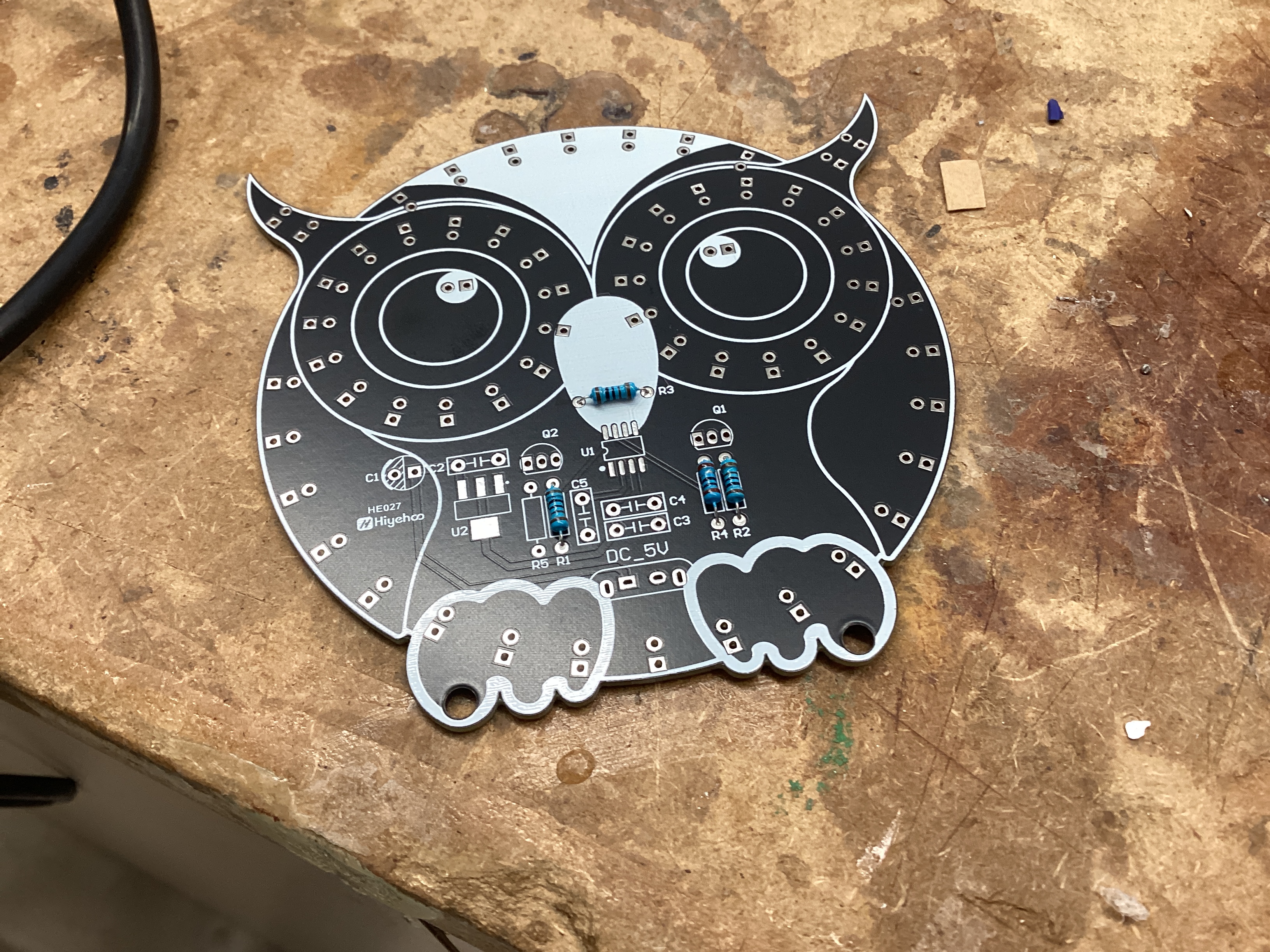
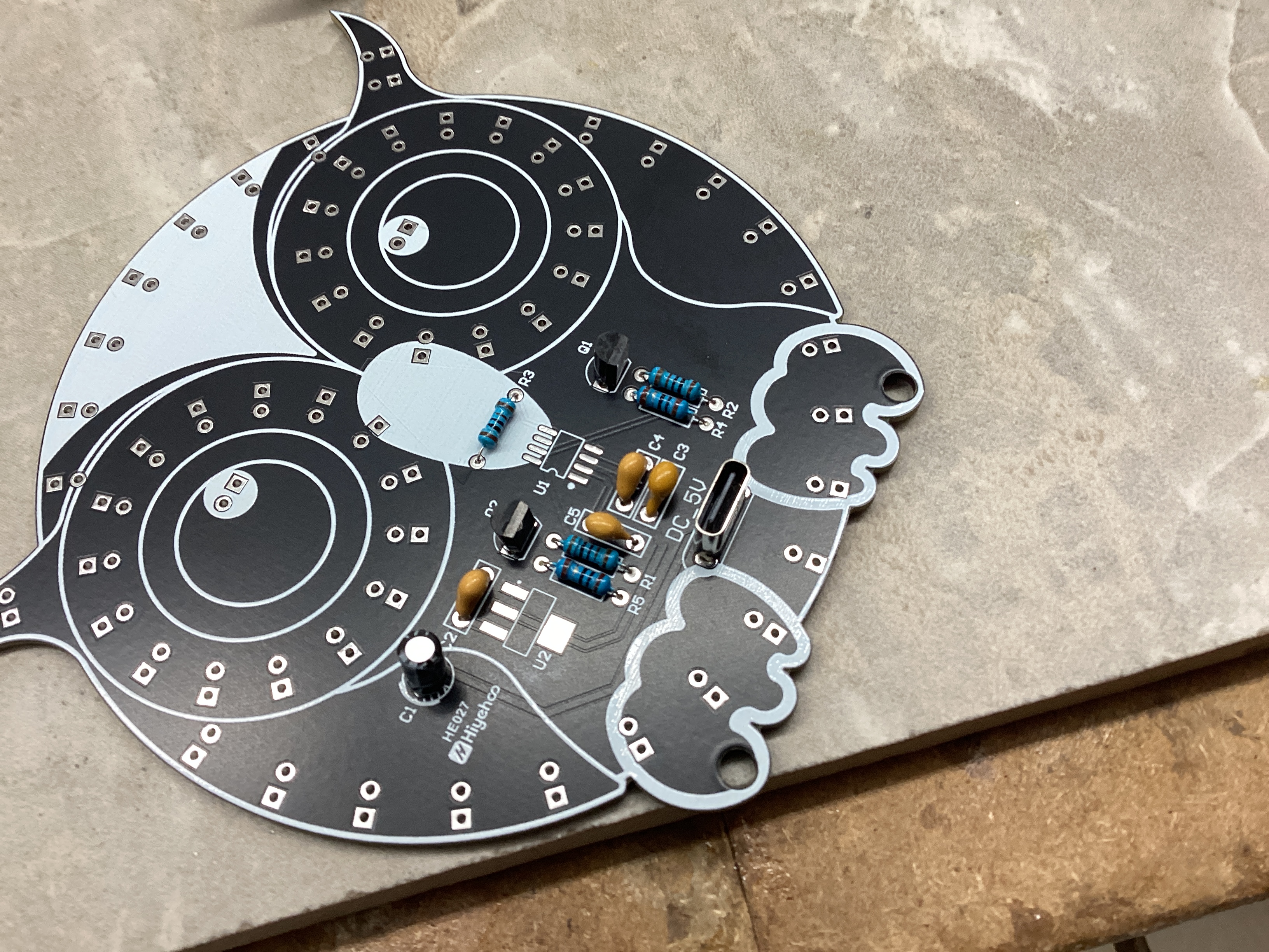
I worked on a mini project to practice soldering. The project is an owl with LEDs which activate by touching a capacitive sensor on the front of the board. While the through hole components were very easy to solder, the 2 ICs on the board with small pin pitches were relatively difficult to solder.
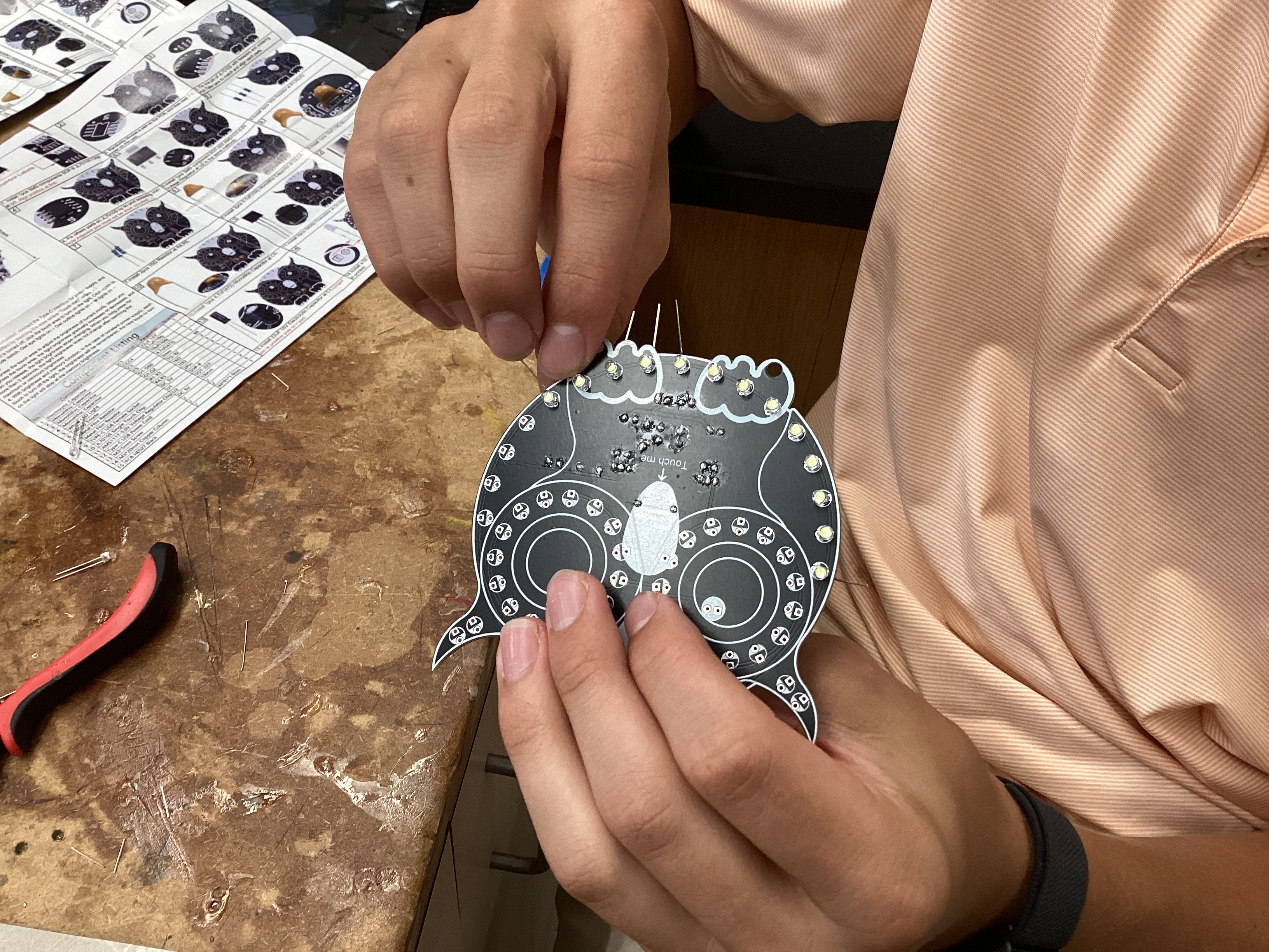
09.30.2025
Today, I finished soldering all of the LEDs, then tested the board. Unfortunately, only the outside ring of lights turned on and the "eyes" did not work. This is due to an issue with an IC. I'm not sure exactly how I will fix it, but I will likely have to de-solder the chip, clean the IC, clean the pads with a solder wick and flux, then re-solder it.
October
10.01.2025
Today, I started setting up my Raspberry Pi 5 with the AI Hat+. I installed the latest release of Pi OS Bookworm onto a microSD card, then plugged the Pi into a monitor to configure it. I then followed this guide to set up the Pi.
-
I started off by setting up PCIe Gen 3.0 by typing
sudo raspi-configto bring up the Raspi-Config CLI tool, then enabling PCIe Gen 3.0 speeds under Advanced Options. -
After that, I ran
sudo apt install hailo-allin order to install the following:- Hailo kernel device driver and firmware (allows Pi OS to communicate directly with the Hailo-8 NPU)
- HailoRT middleware software (runtime that handles tasks such as loading the AI model onto the chip and managing inference execution)
- Hailo Tappas core post-processing libraries (computer vision libraries that handle post-processing tasks such as decoding bounding boxes, converting raw data into masks, and mapping points onto human body parts)
rpicam-appsHailo post-processing software demo stages (Pi OS's camera stack allowing for video recording, image capturing, live feeds, etc.)
10.07.2025
Today, I printed out the bottom plate for my drone, which is where most of the electronics are mounted.
I noticed the following problems with it:
- Holes too big for camera and do not gripping screws
- Camera mount is too weak to support the camera properly
- The npu chip is slightly pressing on camera, causing the camera connector to heat up as well as forcing the plate to bend very slightly
10.08.2025
Today, I focused on getting the AI working on the Raspberry Pi. Up to this point, I was using the pre-existing hailo_inf_fl.json file in Raspberry Pi OS that uses 3 models: yolov8 (object detection/classification), yolov8 pose (pose detection), and scrfd (facial tracking). While the yolov8 models were correctly compiled for the Hailo 8 (the NPU I am using), the scrfd model was compiled for the Hailo 8L NPU, the lower performance version of the Hailo 8. This returned a warning message that I will likely experience lower performance than expected, since the model was compiled for the incorrect architecture. I wanted to get rid of this error, so I looked at the Hailo Model Zoo Github and looked through the models until I found the link for scrfd compiled for the Hailo 8 NPU.
Once I found the correct .hef file, I looked at the hailo_inf_fl.json file to see where the current scrfd file is located. It was located at /usr/bin/rpi-camera-assets/scrfd_2.5g.hef, so I deleted it and copied the new scrfd_2.5g.hef file to the same location to ensure that the json file would work as expected and know where to locate the model. When I re-ran rpicam-hello -t 0 --rotation 180 --post-process-file /usr/share/rpi-camera-assets/hailo_inf_fl.json, I no longer got the warning that the model is compiled for the wrong NPU. Although it would have previously worked fine, I wanted to ensure that everything was as optimized as possible to ensure maximum performance and the lowest power consumption possible.
Additionally, I printed a new base plate. I made slight modifications to the base plate, and it flexes a lot less.
10.09.2025 - 10.16.2025
In this period of time, I worked on refining and iterating on my CAD designs to maximize internal volume, reduce drag and mass, and make sure everything fits. I printed out many different designs, each with very small changes.
Additionally, I finished the owl project by taking a fine tip soldering iron and melting the excess solder paste on the ICs. Doing so got rid of the excess solder paste that was likely bridging some pads and made the owl work perfectly.
10.17.2025
Today, Mr. Dubick taught us how to use Jekyll and GitHub pages. Although I currently use MKDocs for my portfolio, it's useful to know how to use Jekyll in case I want to use it in the future.
10.20.2025
Today, I started off with refining my original chassis design even more. However, I was not very happy with the level of complexity of the parts They were too weak, complicated, and I decided to start fresh by designing a brand new chassis from the ground up. While the original chassis was a heavily modified version of the Source One open-source drone chassis, the new design was my own from the start and was designed around my specific hardware and design intents.
My overall goals for the new chassis were to increase structural rigidity, reduce complexity, support larger propellers, and have better mounting points for the Raspberry Pi and camera (read more details about chassis development here).
10.21.2025 - 10.31.2025
In this period of time, I worked on a mini-project: milling a PCB on the CNC machines in the Fab Lab (read more under the PCB Milling page). Mr. Dubick provided gerber files, and showed us how to use MakeraCAM and Carvera Controller to create toolpaths and run them on the Carvera Desktop CNC machines.
November
11.03.2025 - 11.07.2025
In this period of time, I worked on the new chassis. I made incremental changes almost every single day in order to have strong mounts in the front for the Raspberry Pi and camera module, as well as making sure that things like the power switch and power indicator LED on the bottom of the flight controller board have cutouts in the chassis so they're accessible. Throughout this period of time, I printed 9 variations of the chassis before ending up with one that did everything correctly.
11.10.2025 - 11.14.2025
In this period of time, I started work on the drone's electronics. I tried to solder small capacitors to the flight controller first with solder and a fine tip soldering iron, and it did not work at all. Even the smallest solder in the lab was far too thick for the tiny pads, so melting any solder would flood the pads with solder and would knock the capacitor off the pads. Then, I tried to use solder paste. Although it was easier to precisely apply solder paste to the pads with the paste, it was very difficult to solder with the iron. The reason for this is because the capacitors are so small that heating up end to melt the paste ends up heating up the other end, causing the capacitor to melt the solder and disconnect from the pad. My next idea was to laser cut a stencil out of mylar so I could precisely apply solder paste, but when I tried making the stencil with the laser cutter, the mylar deformed and made the holes too big.
11.22.2025 - 11.30.2025
No school - Thanksgiving break.
December
12.01.2025 - 12.10.2025
In this period of time, Mr. Dubick taught the class about designing circuits with Arduino and programming in C. Although I was already experienced with creating the physical circuits, learning to code in C was very helpful and will likely help me understand the ArduPilot code better in the future.
12.11.2025 - 12.15.2025
In this period of time, I worked on the drone's electronics. Instead of using a soldering iron and normal solder, Angelina recommended using solder paste and hot air to solder on surface mount components. Although it was still challenging, it was a lot easier than using solder and a traditional iron.
12.16.2025
Today, I milled the topography out of a block of hardwood (more in this under Topography). Milling the block took around 6 hours, so while it was milling, I worked on documentation.
12.18.2025
I spent today catching up on documentation.
January
01.14.2026
Today, I continued work on the redesigned chassis. I designed a new part that acts as both landing gear and as a stiffener. It mounts flush under the main body with 8 mounting holes and has extruded pegs to keep the drone from sitting flat on the floor and absorb shock under landing. I will print prototypes out of PLA and print the final product using a mix of TPU and PETG; the main plate will be PETG and the extruded pegs will be TPU for better shock absorption.
01.15.2026
Today, Mr. Dubick gave me soldering kits to practice soldering fine components, since I have been having trouble soldering the electronics on my board. Also, I added mounting holes to my redesigned chassis and printed out a majority of the parts.
01.16.2026
Today, I started using the soldering practice kits. The kit included a wide variety of SMD components, from larger 1210 resistors all the way down to tiny 0402. Additionally, it included various ICs with many small pins, similar to the STM32F767ZIT6 that I had trouble soldering on Version 1 of the flight controller. I think they'll be helpful for developing my soldering skills.
01.19.2026 - 01.27.2026
In this period of time, I continued work on the soldering kits. I worked my way down from big components to small components; I started with 1210 resistors and worked my way down to a 44 pin SMD chip. The first time I soldered the chip, I had a lot of bridges between pins, and Dr. Taylor recommended that I use solder wick to remove excess solder. When I used the wick, it removed all the bridges and left the chip cleanly soldered.
01.28.2026 - 01.30.2026
Since I had been soldering for over a week straight, I decided to take a short break and continue chassis development. I continued work on Version 3 of the chassis, which had much more internal volume so I could keep the thick battery wires internal, as well as more room for electronics. I did this since I am considering switching to a new electronics design based on the Nucleo F767ZI, which is a pretty large board.
February
02.02.2026 - 02.06.2026
I was very sick this week and did not do any work.
02.09.2026 - 02.12.2026
I was recovering from being sick this week and spent the first two days catching up on documentation. In the rest of this week, I did some CAD work on Version 3 of my chassis.
02.18.2026 - 02.20.2026
This week, I made significant progress on the redesigned flight controller. I received the Nucleo F767ZI board, and worked on a hat that sits on top of the Nucleo board's female headers. The new board contains the following:
- XT90 input
- 5V BEC
- 3.3V BEC
- I2C ports for barometer and magnetometer
- Serial port for radio
- SPI port for IMU
- Pads for NEO-M9N GPS module
By the end of the week, I finished the design and made the toolpath in MakeraCam so I could mill it out first thing next week.
02.23.2026 - 02.27.2026
In this week, I continued work on the electronics. I kept milling out boards, and I encountered many issues. The first board I milled, many of the smaller pads didn't cut properly and were all bridged. Since I had tried so hard and made no progress, and the March 5th deadline was approaching quickly, I made a decision to design a simpler board that only had a 5V step down, the radio module, and the IMU. I chose to cut out all other hardware temporarily, such as the auxiliary magnetometer, barometer, GPS module, and Raspberry Pi companion computer. Since cutting these components out significantly cut down the amperage needed, I could power this board solely by stepping down the VBAT pin from the ESC to 5V with the Pololu D36V50F6, rather than having an XT90 input and having to solder on thick power leads.
After designing the new board in KiCad, I milled it out. Originally, the design was double sided, and when I milled the other side, the front and back sides didn't line up. Rather than spending time troubleshooting this issue, which would have been very time consuming, I altered the design to fit all of the traces on the front side, eliminating the need for milling both sides. Once I finalized the design, I milled it out on a single sided PCB, and all the holes and traces rendered correctly.
However, since I had to fit many traces into a small space and was constrained to only using the front side, I set a majority of the traces to 0.25mm in thickness. While this easily passes the built-in Design Rules Checker feature in KiCad, this meant that the milled out traces on the board were very weak. When I was soldering, a few traces broke, including the main 5V line that literally powered everything from the IMU to the entire Nucleo F767ZI board itself. I then tried soldering all the wires directly to the Nucleo F767ZI board. I figured that it would look messy with many wires, but at least it would be wired together. Once I did so, I made a custom build of ArduPilot, but it didn't work properly and I knew that I would have to spend a lot of time and do a lot of research to fix the issues I encountered.
March
03.02.2026 - 03.05-2026
Since my flight controller wasn't working, I decided to temporarily pause development of the custom flight controller and decided to use a Seed Studio Xiao RP2040 board to simply send PWM signals to the ESC to get the motors spinning. I did so in order to have a demo ready by the March 5th due date. I soldered the 4 motor pins (M1-M4) from the ESC to the RP2040, soldered the VBAT and GND pins to the 5V BEC, and soldered the 5V output and GND to the RP2040 to give it power. I then used Claude Sonnet 4.6 to generate two codes: one that spins the motors at minimum speed to make sure that everything works, and one for me to try and take off.
I first ran the code that made the motors spin at minimum speed. I recorded them spinning in slow motion at 240 FPS and switched the propellers around to match the direction of the motor rotation. I then ran the code that provided enough power to take off. Unfortunately, when I ran the code, the drone did not take off properly. The right side overpowered the left and the left side propellers smashed into the floor and broke. Additionally, in this crash, the left side arm supports broke. Although I'm not certain, I suspect that this error was due to the battery placement. Since the battery is by far the heaviest component of the drone, even if the battery is slightly off center, it will cause massive instability since it makes up 35% of the entire drone's mass. In the current design, the battery is located in the front and is located 2mm to the left of the center. When I attempted to take off, the back right side lifted the most, since the front left was the heaviest and had the most downward force on it.

This test revealed both good aspects and bad aspects of the drone, such as:
Good Aspects:
- The motor/ESC/battery combination is more than powerful enough to lift the drone. I only ran 30% throttle, and it was taking off. Additionally, the ESC and motors ran reliably, proving that all my solder joints are very solid.
- The arms and arm supports are strong enough to sustain the forces from the motors and propellers
Bad Aspects:
- The chassis's center of gravity is not in the middle and is causing imbalances. Although ArduPilot can compensate for this by using data from the IMU, it is still better to make the chassis as balanced as possible as to not have a reliance on software for balancing.
- The custom flight controller is still not working, and I will most likely have to get it manufactured overseas since the milling machines in the lab are not precise enough to manufacture a board to my specifications.
Action items to complete before April 12th:
- Modify chassis with the following aspects:
- Move battery to center
- Add fillets to strengthen arm supports
- Add ribs to arms to make them stronger
- Finalize FC design and get it manufactured
- Research more on building a custom ArduPilot build and build the firmware.
03.09.2026
start work on chassis v5